Gear Rack
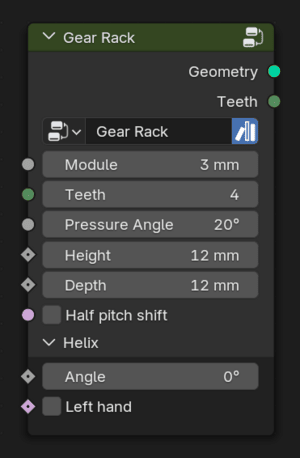
The Gear Rack node.
A rack, or toothed bar, is simply an unwinding of a cylindrical gear and can be thought of as a gear with an infinite diameter. The important sizing variable, like any other gear, is the module. Increasing the tooth count will only increase the length of the rack. The same rules as any other gear meshing apply: to fit a gear to a rack, they must have the same module value and pressure angle.
Inputs
 Module
The module for this gear.
 Teeth
TeethThe number of teeth on the gear.
- Pressure Angle
The pressure angle in degrees. This effects the shape of the gear as it does in other types of gears. This directly changes the slope of the sides of gear without changing the pitch, resulting larger or smaller tip sizes. In most cases, this value should match the pressure angle of the gear to which it is being meshed.
 Height
The height of the rack. This is measured from the base to the top of the tooth.
- Depth
The thickness of the rack.
- Angle
The angle of the helix. This defaults to \(0^\circ\) to form a straight gear rack.
 Left Hand
The direction of the helix.
Outputs
 Geometry
The output gear rack geometry.
- Teeth
For convenience, the number of teeth on this gear.
This node doesn’t output a reference pitch radius like circular gears. The origin of the rack is at the pitch center of the first cog of the rack. This means that alignment with a circular gear can usually be achieved by moving the gear (or rack) orthogonally away by the gear’s pitch radius. This is shown in the first example below.
Examples
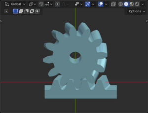
Helical gear to helical rack example.
This example shows a helical gear on a rack. Like any other helical gear set, the angles must match but one must appose the other. To mesh, this ratio required the gear to have a half pitch rotation.
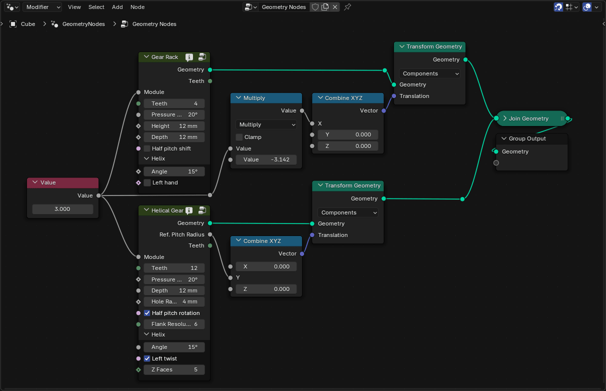
Geometry node for this helical gear to rack example.
The rack is translated on the X-axis one tooth (\(m\times\pi\)) to center the rack under the gear. The gear is translated along the Y-axis so that its pitch radius aligns with the rack.