Working Notes
This chapter captures some notes that I needed as this library was developed.
Spur Gear Geometry
The gear’s module (\(m\)) and the number of teeth (\(z\)) are the main inputs to a gear’s size. Two meshing gears must have matching module and profile curve values. The profile curve has a role in the shape of the flank and is better explained by the references above. The default is a reasonable value. The module declares the length of the addendum, that part of the cog above the pitch radius, as well as the length of the dedendum, the part of the cog below the pitch radius.
Two gears coincide at their pitch point and the diameter of the gear at that point is known as the pitch diameter.
Tip
If you want a physically larger gear, increase the module size.
As mentioned earlier the module is the length of the gear’s cog above the pitch radius, so the diameter at the tip is,
To construct a set of gears with a specific diameter start with the number of teeth and the target diameter, then derive the module,
Spur gear on plane
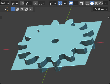
Here is an example of creating a gear that fits into a specific dimension using geometry nodes. We start with the TARGET shown as a rectanglular grid that is 80mm square and we want to fit a 14-tooth spur gear onto it.
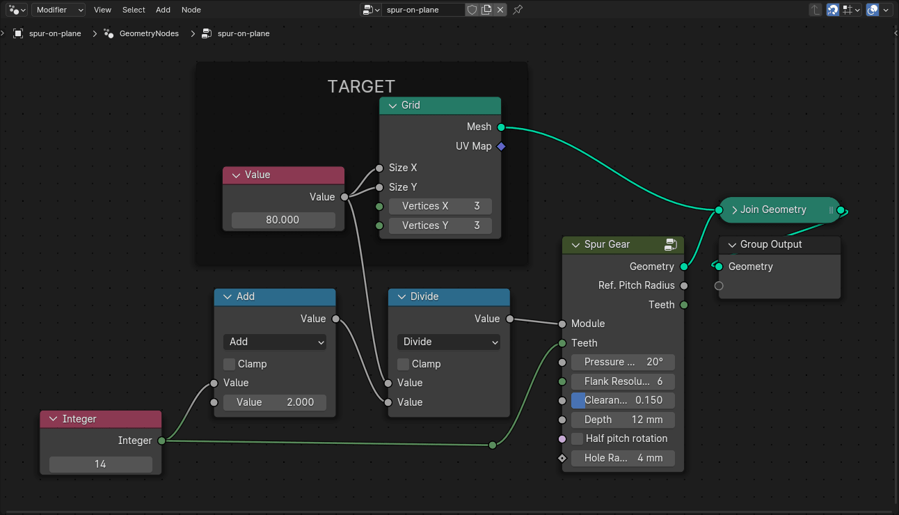
Geometry nodes for calculating the module from a target diameter.
Remember that the very first step to working with these nodes is to set the Scene Properties to the proper Units. Refer to the Modeling Setup section for more details.
Angle at base
The shape of a gear is controlled by the pressure angle. The angle controls the width at the base as well as the spur tip. Gears with small pressure angles will have a wider root and thicker tip than those with a larger pressure angle.
Regarding clearance
The clearance value for gears defines additional space added to the root between two cogs to allow for the passage of the tip of a cog of an opposing gear. When gears are cut, these are created somewhat naturally by the machine tool and usually form a circular shape. That is not strictly necessary and, in fact, it would create more topology than I was willing to add. The whole depth is the total size of the gear’s cog, from tip to root,
The default clearance is usually sufficient.
Bevel Gears
If you visualize spur gears as two cylinders rotating against each other, a pair of bevel gears can be seen as two cones rotating against each other. These cones are known as pitch cones because the pitch radius slides along the edge of the cone and, just like spur gears, they are sized according to their module and number of teeth.
The first figure in the next section shows this visualization from a side view.
The Pitch Cone
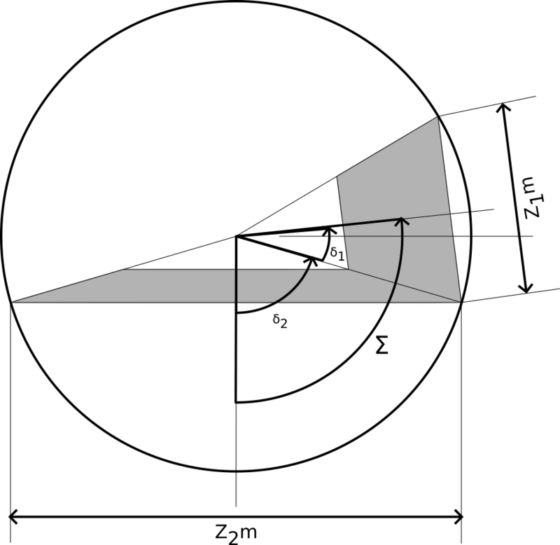
Reference Cone Angle
This drawing shows a generalized bevel gear set with the pitch cone angles (\(\delta_1\) and \(\delta_2\)) where the sum \(\sum\) doesn’t equal \(90^\circ\). When the number of teeth (\(z\)) in the pinion is equal to the number of teeth in the bull gear (a gear ratio of \(1:1\)), and the gears are set at a \(90^\circ\) angle, they are known as miter gears.
The sum of the pitch cone angles is known as the shaft angle, usually annotated as \(\Sigma\),
Bevel gears must be considered in pairs since the tooth counts will affect the pitch cone angle. For the miter gear described earlier (set at a right angle with \(z_1 = z_2\)), the above calculation will result in a pitch cone angle of \(45^\circ\).
It is typically necessary to provide the pitch cone angles during construction of the bevel gear, which can be determined with this derivation,
For bevel gearing, the reference diameter \(d\) is known as the pitch diameter. The equations should look familiar (\(m\) is the module of the gear),
The cone distance (\(R\)) defines the linear distance between the reference points at the intersection of the reference diameters,
Face Width
The face width (\(b\)) is the distance across the gear teeth and length should match for a bevel gear pair. Not much is said about this but the going recommendation is,
Gear Racks

Basic dimensions of a gear rack
Where,
As with other types of gears, sizing a rack depends on the \(m\) value and the shape of the cog depends on \(\alpha\). As \(\alpha\) increases the tip and root get narrower. The center of the tooth is the pitch line and is analogous to a circular gear’s pitch diameter.
Not shown in the diagram is a small clearance below the root (between the gears). This clearance is defined in terms of a factor multiplied by the module to set the depth and is hardcoded to \(0.25\).