Modeling Tips
Modeling Setup
Gears are sized in millimeters. You can save yourself lots of sizing pain by setting units to millimeters in your scene properties. All the node images in this reference document use these Units changes so the distances are displayed in millimeters (3mm instead of 0.003).
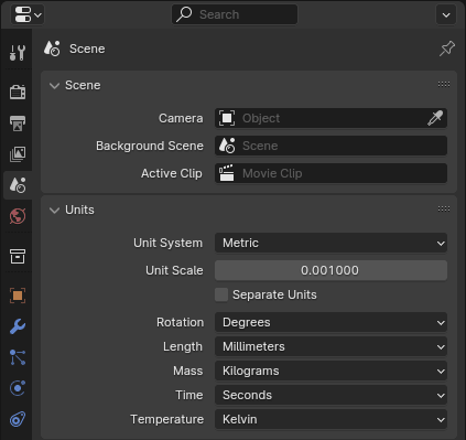
The Scene Properties panel with Unit Scale and Length adjusted to millimeters.
Aligning Gears
All of the node groups in the gearbox present mechanisms for aligning meshed gears.
- Ref. Pitch Radius (output float)
For circular gears this is the distance from the origin of the gear to the pitch circle.
- Pitch height (output float)
For rack gears this is the distance from the origin to the pitch line.
- Half pitch rotation (input boolean)
If true, will rotate the gear \(1/2\) a gear tooth.
- Helix / Angle (input angle)
For any gear with angled teeth the angle must match to mesh with the opposing gear.
- Helix / Left twist (input boolean)
For gears with angled teeth the direction of the helix angle of one gear must oppose the other gear.
All circular gears are created with the origin in the center and a tooth aligned on the X-axis. This is apparent on straight spur gears, on helical and herringbone gears this tooth is at the lowest Z-axis of the gear. I’ve tried to be as consistent as possible so that all gears can be meshed using the same method.
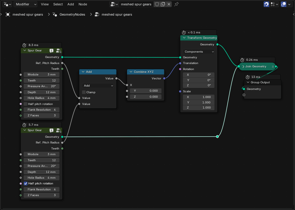
Join both gears in the geometry.
Add the Ref. Pitch Radius from each gear with a math node.
Use a Translate Geometry node to move one gear that distance. This will align the two gears along their pitch circles.
Use the Half pitch rotation option if necessary to align cogs.
Smoothing
My personal preference is to use normal smoothing and tweak the angle to my liking. In most cases this seems to be \(50\%\) but experimentation is advised. This simple smoothing will leave the gears mathematically correct and are most likely to work if you are printing gears.
I have experimented with additional subsurface smoothing to good effect. Due to the nature of the Catmull-Clark algorithm, it is wise to preface the subsurf with a bevel moderator. The following example illustrates this (the smoothing example node group is included below).
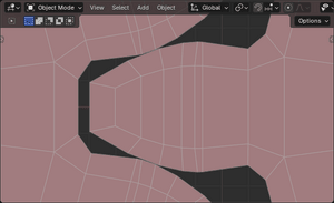
Closeup viewport image of two spur gears meshing.
The pitch radius output was used to precisely set the gears. Note the tightness with this simple setup.
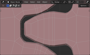
After adding a bevel (Offset, 0.2mm, 1 segment, \(30^\circ\) angle).
The tightness is maintained, even with a simple bevel. The bevel pulls the surface away at its specified offset but keeps the meshing intact.
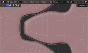
After adding a subsurf modifier with 2 levels.
You can see the effects of the Catmull-Clark mechanism which has pulled more of the gear surface away. Contact between gears is probably fine but you would not want to do this with thin gears. Also take note how subsurf has stretched the edges that form the flank resolution of the gear.
Node group used for this example
Experiment with Z Faces, which adds faces along the depth to help control the effects of smoothing.