Bevel Gear Set
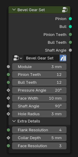
The Bevel Gear node.
The Bevel Gear Set group generates two bevel gears, pinion and a bull gear, matched to one another. Typically, the term pinion refers to the driving gear but it is used here to distinguish one gear from another. The reason bevel gears are provided in pairs is because changes in tooth counts on either gear will cause cone angle changes. This will become apparent as you use the toolkit. Both pinion and bull gears have their origin at world center, with the pinion translated to properly oppose the bull gear.
See the section on Bevel Gears in the Working Notes for more detail on the math used to generate this node group.
Inputs
 Module
The module for this gear.
 Pinion Teeth, Bull Teeth
The number of teeth on the gear.
 Pressure Angle
The pressure angle in degrees. This effects the shape of the gear and plays a role in meshing. The default of \(20^\circ\) is reasonable for most gears.
- Face Width
In a spur gear this would be known as the depth, basically the length of the cog.
- Shaft Angle
The purpose of bevel gears is to change the rotational direction of a gear set; this attribute sets the angle. The default is \(90^\circ\) which is likely for the majority of bevel gears.
- Hole Radius
The size of the center hole. This may be zero. The upper bound is constrained so the hole can’t be larger than the dedendum.
- Flank Resolution
This integer value sets the resolution of the sides of the gear cog. The default sets a reasonable default but set this lower if to control vertex count. Any large value may be reduced by distance merging in the implementation.
- Collar Depth
This adds some control over the length of the collar or spindle extending from the part of the gear away from the gear teeth.
Outputs
 Pinion, Bull geometry output
Each output generates a gear in the bevel set.
- Pinion, Bulll teeth count
For convenience, the number of teeth on this gear.
- Shaft Angle
For convenience, the shaft angle this pair was set at.
Examples
Miter gears
The miter gear is the simplest example. Note that the object origin for both gears is the apex of the pitch cone (this is a little easier to see if you click on the image to view it in full resolution.) This allows relatively easy alignment if you had to do this manually.
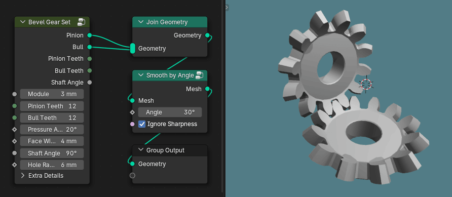
A miter gear: both gears have the same number of teeth and the shaft angle is \(90^\circ\).
Bevel gears with 1:2 ratio
This example shows a bevel gear set with more teeth on the bull gear than the pinion. The shaft angle is still set at \(90^\circ\).
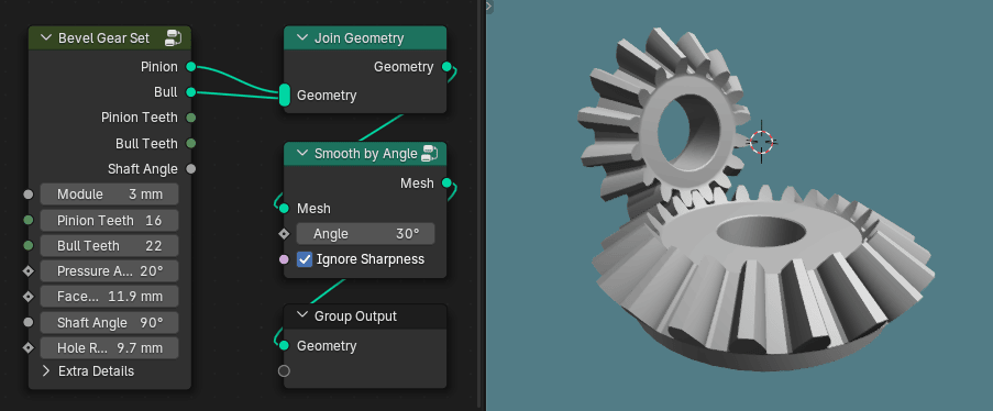
Pinion with 16 teeth, bull with 32
Multiple bevel gear sets
Multiple bevel gears can be employed in more complex configurations. As with spur gears the module must be identical, however, changing the number of teeth in a bevel gear set will alter the pitch cone apex. Probably the best approach is to use only the gear geometry from a single Bevel Gear Set node as shown below.
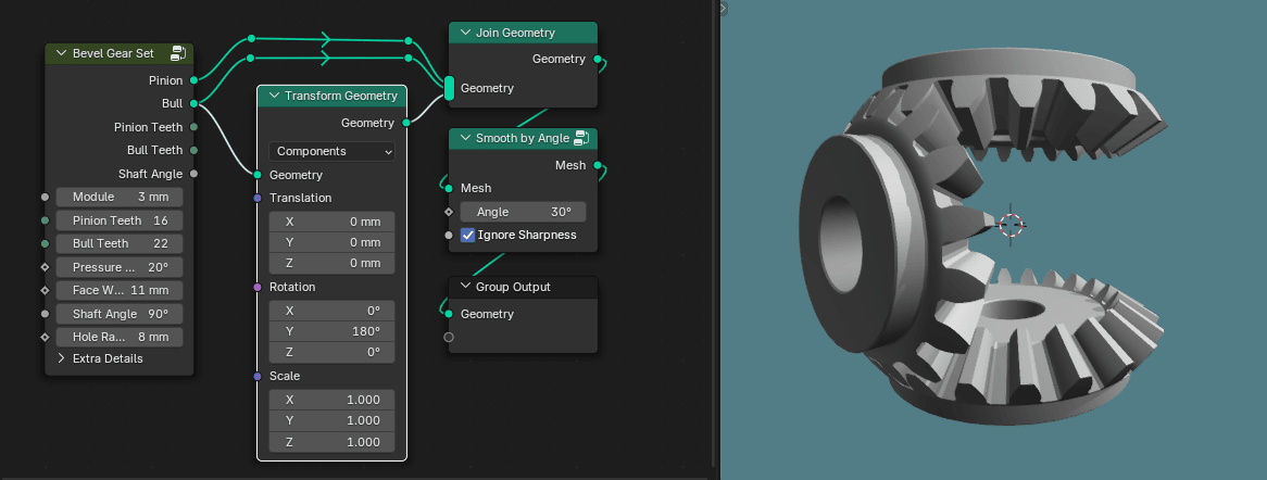
Pinion with 16 teeth, driving two bull gears with 32
The bull gear in this configuration was simply rotated \(180^\circ\). The cogs lined up and didn’t need any other adjustments.